MRMR 2001#
The “Mining Rock Mass Rating”, MRMR, system was first presented by Laubscher in 1977 [1], formalized in 1990 [2] and updated in 2001 [3].
The following makes reference to the MRMR 2001’s version.
The main aspect that make this version different is the consideration of veinlets into the calculations. This transforms the way the rock strength and the discontinuities frenquency are evaluated.
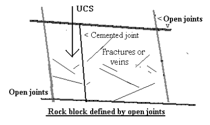
Figure 1: Structural terms.#
Joint condition is calculated simillarly, without considering the groundwater presence and including and extra adjustment factor related to the joints infill hardness.
Adjustment factor are the same, even though a new one is included to include the groundwater.
Parameters#
The following parameter descriptions are based on the 2001 version [3].
Rock Block Strength#
The rating assigned to the calculated RBS is taken from the following figure:
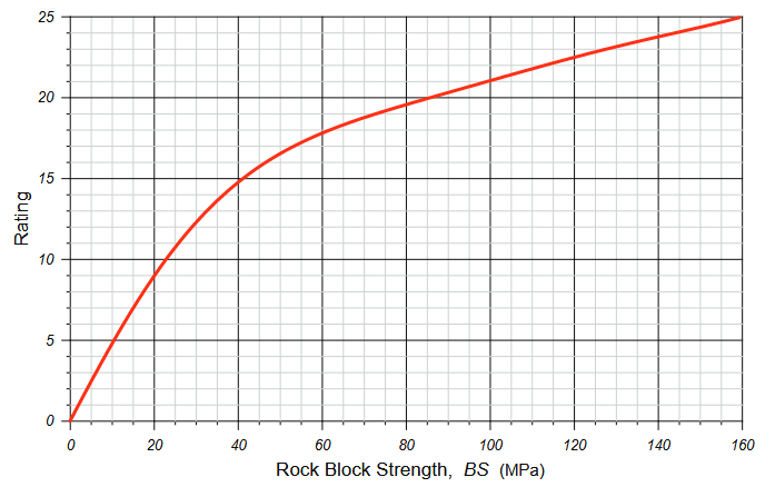
Figure 3: Rock block strength rating as a function of rock block strength.#
Which can roughly approximated to:
Structures Spacing#
The IRMR system accounts for two types of discontinuity spacings:
Open Joint Spacing#
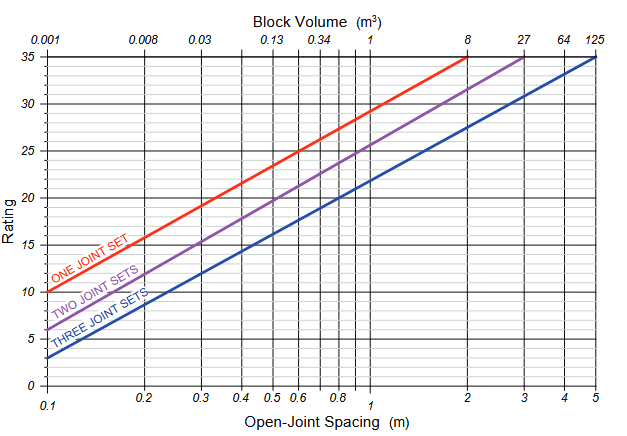
Figure 4: Rating for open joint spacing.#
The curves can be formulated as:
Cemented Joint Spacing#
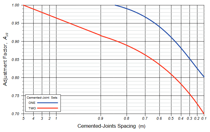
Figure 5: Adjustment factor for cemented joints where the strength of the cement is less than the strength of the host rock.#
Usually, this curves are defined linearly piece-wise.
Joint Condition#
Large-scale Expression#
“Sub-section A caters for the large-scale expression of the feature, such as across a drift or in a pit face.”
Description |
Adjustment |
|---|---|
Wavy multi directional |
100 |
Wavy uni directional |
95 |
Curved |
90 |
Slight undulation |
85 |
Straight |
85 |
Small-scale Expression#
200mm x 200mm
“B assesses the small-scale expression and is based on the profiles shown…”
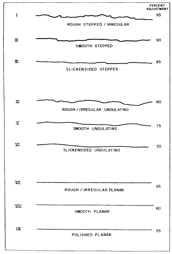
Figure 6: Joint roughness profiles.#
This is the same as in MRMR 1990.
Description |
Adjustment |
|---|---|
Rough stepped/irregular |
95 |
Smooth stepped |
90 |
Slickensided stepped |
85 |
Rough undulating |
80 |
Smooth undulating |
75 |
Slickensided undulating |
70 |
Rough planar |
65 |
Smooth planar |
60 |
Polished |
55 |
Wall Strength Contrast#
“Section C is applied only when there is a distinct difference between the hardness of the host rock and that of the joint wall”
This means that Factor C is only activated or modified when there is a noticeable contrast in mechanical properties between:
The intact rock mass (host rock), and
The material or surface along the joints (joint walls), which might be altered, infilled, or weathered.
This is analogous to its implementation in MRMR 1990.
Description |
Adjustment |
|---|---|
Joint wall alteration weaker than wall rock and only if it is weaker than the filling |
75 |
Infill#
Laubscher [4] reduced the available filling option to just two options.
Some practitioners use the MRMR 1990 version of infill adjustment factors. Some others just set this factor to 100.
Description |
Adjustment |
|---|---|
Gouge thickness < amplitude of irregularities |
60 |
Gouge thickness > amplitude of irregularities |
30 |
Infill Hardness#
Hardness |
Type |
Adjustment |
|---|---|---|
5 |
Apatite |
95 |
4 |
Chalcopyrite/Fluorite |
90 |
3 |
Calcite/Anhydrite |
85 |
2 |
Gypsum/Chlorite |
80 |
1 |
Talc/Molybdenum |
75 |